For a long time I have used two mics for my amateur radio setup, a Heil PR-40 for my HF rig and A Heil PR781 for my ID-5100. I received good audio feedback all around and every time I tried to get down to 1 I’d get noise in one or the other rig and I’d just go back to what worked.
Recently I’ve been doing some writing work and that’s required me to have conference calls a couple of times a week. The mic on the camera is decent, but I have these beautiful professional mics right next to me, and it was killing me not to use them.
I ended up purchasing a new tool to help me integrate. The Focusrite Scarlet 2i2.
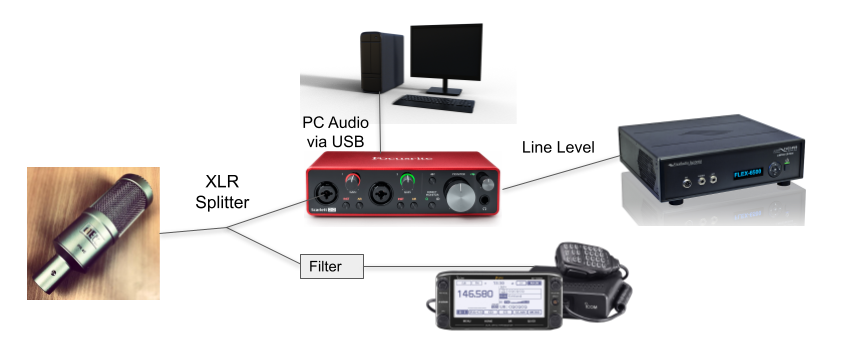
Now, instead of the PR-40 going straight into the balanced input of the Flex 6500, it runs into the 2i2. The 2i2 has 2 line level outputs on the back. I run that to the Flex 6500 and it doesn’t know the difference. With the Focusrite’s USB connection to the PC, it sees it as a sound card that I can run into Zoom or Google Meet. No sweat.
This still leaves the problem of feeding the ID-5100. I’ve done this for now.
[Image Removed – It was a hot mess.]
I received feedback from the folks on the Atlanta Radio Club Sunday Night Net that the XLR Split leaves my FM audio with a high pitched whine in it. So, as the graphic says, I’m going to build an adapter to come out of the other Scarlett 2i2 line out port and step the audio down to Mic level for the 5100.
Parts are on order. I’ll update later this week on how things go.
17-Feb-21: It’s Later. Here’s what happened.
The device I made didn’t work as planned. I also purchased a commercial device and tried it on the line to the ICOM 5100. It didn’t like that either. So I purchased a mic filter that seems to mitigate some of my audio issues and here’s what the chain looks like.
If you have any thoughts on this, hit me up on Twitter @N4BFR.
It’s a nice confluence of my fandoms, I love old technology, I love clocks and I love Raspberry Pi’s, so when I found a Luminator 7×90 Flip Dot display on eBay in early January, I bought it. This is the fairly-detailed, well illustrated story of how I brought a 90’s sign together with a low cost but powerful computer.
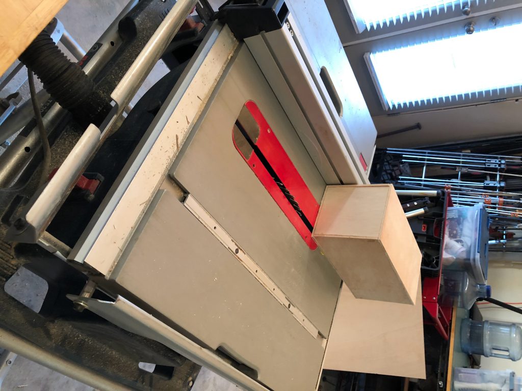
A lot of times the background noise in my shack while I work on code projects or just putter around is Adam Savage’s Tested on YouTube. Yes, the MythBusters maker known for blowing stuff up puts on a great channel of builds and tips. Last week he did something called a “Real Time Box Build” and I said, “I can do that, and I have just the project for it. So, I present my box build in pictures.
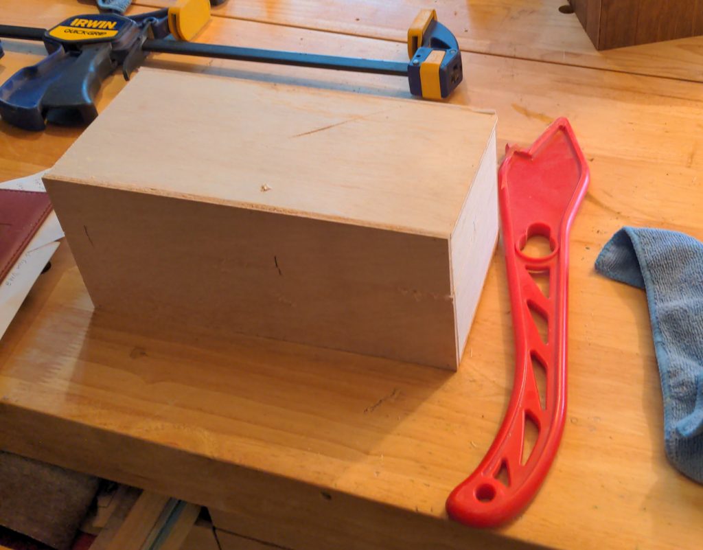
The shape is done, time to split it open.
Ready for sanding and finishing,
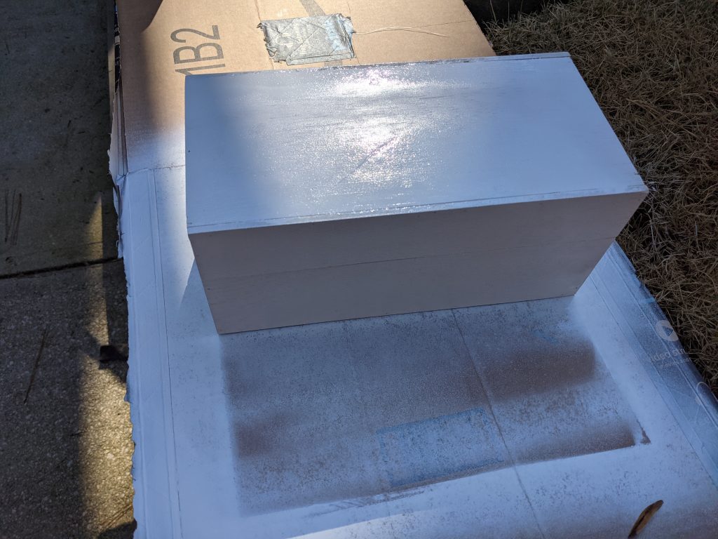
Just a coat of spray paint
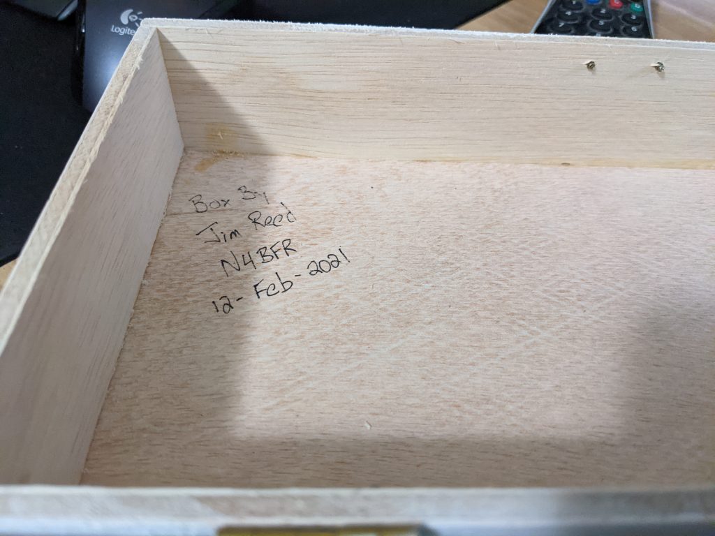
Had to sign my work
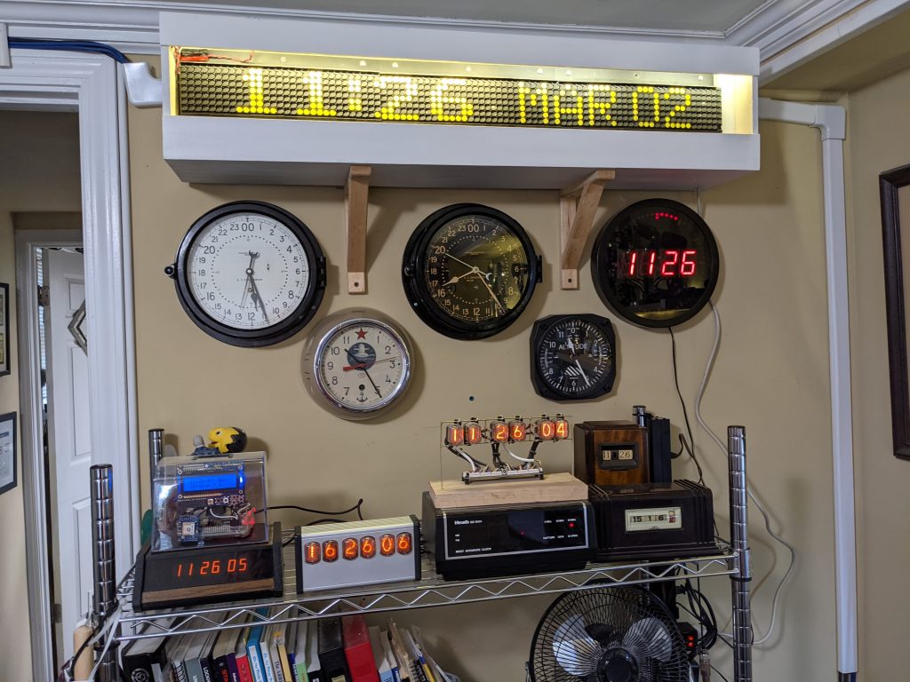
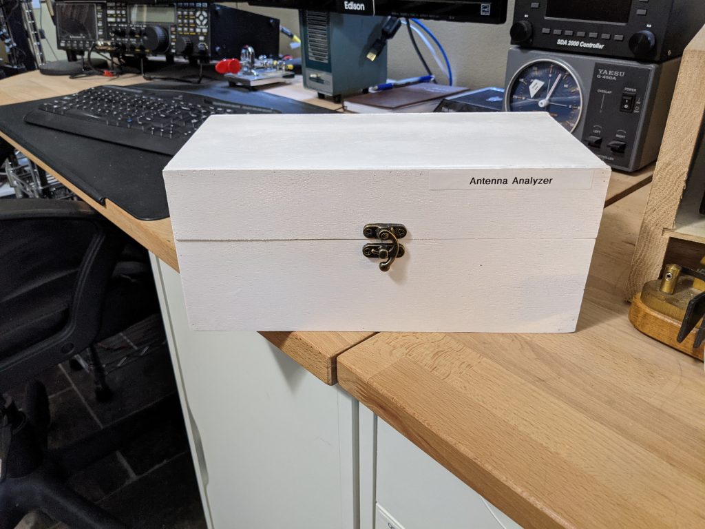
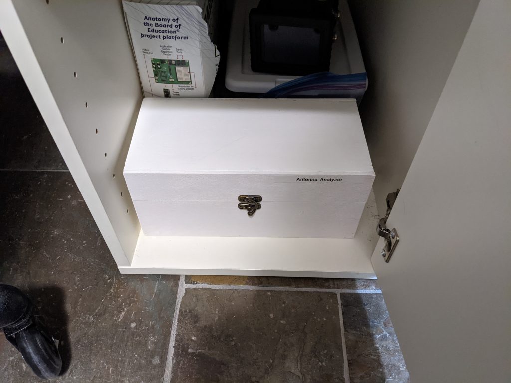
The final exterior in my shack
Tucked away in the closet until needed.
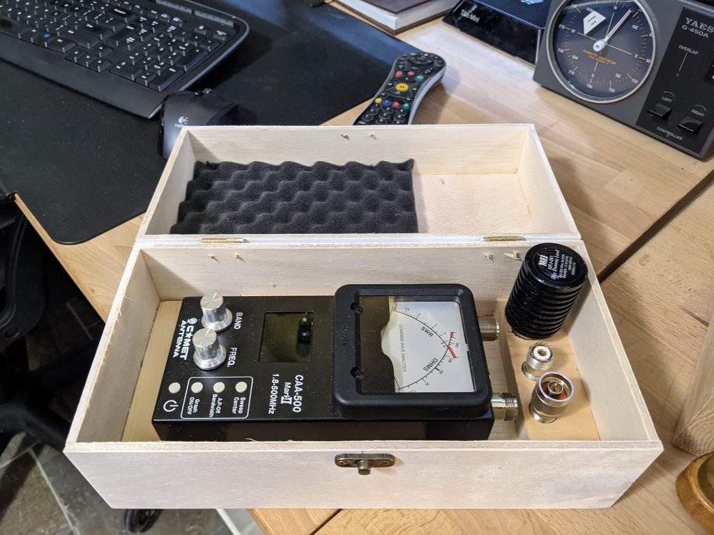
A look at the progress of the Antenna Analyzer box.
The Antenna Analyzer box protects my Comet CA-500 meter much better than the original cardboard box I had been dragging it around in. It also gives me some quick access to the three accessories I use the most with it. Those are a dummy load, a N to PL-239 adapter and a barrel connector.
I know Adam usually doesn’t do finishing on his storage boxes but I had just a little bit of white spray paint left from another project, so I hit the outside with a bit. I also added the necessary label (my goal is to have more labels than the Bat Cave at some point) and I signed it on the inside.
Big thanks to Mr. Savage for his easy to understand tips. I particularly like the concept of “build the box, then cut it open” versus building two halves. I also found his tip on using a pin-nailer for assembly very helpful so I invested in a Ryobi that works very well and doesn’t need a compressor.
I also need to give a huge shout out to my friend Karen who let me user her basement wood shop. I have done some woodwork at Decatur Makers, and will do so again, but this allowed me a little extra social distancing which was a relief for me.
As you might guess by the headline, this is the first of several projects for me. Part 2 will be a yarn box my wife requested to keep our kittens out of her skeins. Part 3 is a large frame for my Flip Dot Sign project. So check back for more.
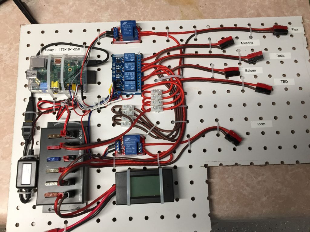
As one of my earlier projects, I set up a Raspberry Pi with some relays to control my systems remotely. This allows me to warm things up from the couch before I head to the shack, or if COVID ever goes away, to fire up the radio remotely.
2016 photo of the relay panel.
So it’s been several years since I made any updates to the Raspberry Pi that makes all that work. I remember rolling back from a Raspbian update because it broke some functionality and I wasn’t in a place to spend time on it. I finally found the time this week, 3 YEARS later.
As I write this it is January 15, 2021
So I decided to start from the ground up with the latest version of Raspbian and reinstall WebIOPi, which is the software I am using. WebIOPi allows me to use the GPIO pins to control the relays using a web interface. I had spent a little time customizing it for my shack so I wanted to keep using it. Unfortunately it hasn’t been updated in 4 years.
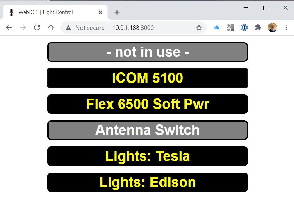
My quick GUI for controlling lights and radios.
After struggling with the latest version of WebIOPi (0.7) and dealing with “invalid syntax in thread.py” and “Attribute error” issues related to my Pi 2B, I found my savior on GitHub. https://github.com/doublebind/raspi
Follow the instructions theree and you are good to go. I’ll be pleased if it will run another 3 years with no need for updates.
Last winter, early post retirement, I was tinkering around with one of my many clocks one day and added the chimes of Big Ben to it. Whenever I would visit my grandparents growing up, I would hear their clock that struck the Windsor Chimes and I always thought that would be a fun project.
This was fairly straightforward, I grabbed some sound files from the UK Parliament website and one other source for the 45 minute chime, and did a little editing. Work done implemented via CRON in a couple of hours, fast forward on to other things.
A few months later and I am on the phone with my mother and she hears the chimes in the background. She starts reminiscing about the sounds and her parents clock and I agree to make something for her.
This video documents the major elements of the build but here’s the parts list:
I had all the sound files to go on from my build into my exciting digital clock, so no additional work done there. One tricky bit was to get the hourly chime to trigger at about 59:40 after the hour so the big ben bell would start striking the hour right at the top of the minute. Since CRON works on minutes, I solved that by making a 59 second file. So the file starts at 59 after but plays a silent section for the first 40 seconds before the chime.
How the hourly Big Ben bell plays: CRON is programmed at xx:59 to trigger a shell script that first plays the chimes, this is the file mentioned above. It then triggers the Big Ben bell sound, and loops the appropriate number of times for each hour. Here’s an example of the code for 9 o’clock. There are 12 files, 1 for each hour.
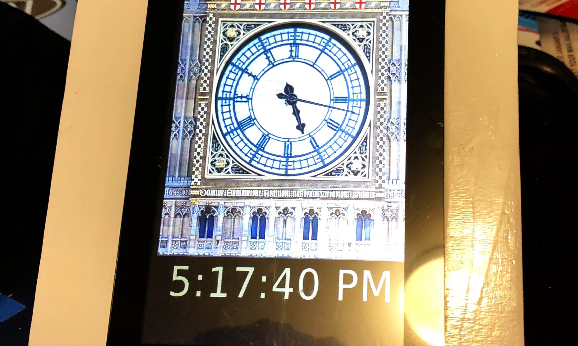
A couple of new skills for me were achieved on this project. The first was working with JavaScript clock elements for an analog clock. This came together by adding the face of the Great Clock as a background image, editing the photo for size and removing the hands from the face. I then found some similar looking clock hands and did a JavaScript analog clock overlay via HTML. Adjusting the pivot points for the hands took some time, they would drift around the clock face until set just right.
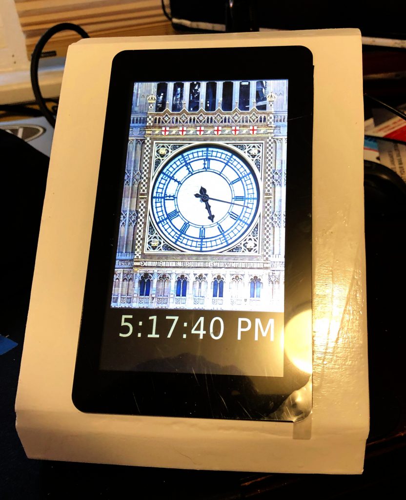
The other element to this was hardening it so it was hands off for mom. With her being 1,000 miles away, I couldn’t do a local install so it had to be right. I had her send me her WiFi info so I could pre-program it on the card. I chose USB powered speakers with an on-cord volume control so she could just lift the touch screen off the case to adjust. Also added a “kill switch” to the back for easy shut down. Finally I included a backup USB card in the case incase the current one is corrupted and I keep an image on my NAS as well if needed.
I did not put a RTC in the Pi. Partially because some of the GPIO ports I wanted we used by the Touch Screen and partly because I had the clock programmed to get NTP time via WiFi so there would be no updating needed.
The Hardware Build
I started with the standard elements I knew the Raspberry Pi 3B+. I chose the B+ because I didn’t need the horsepower of a Pi 4 for a basic display and I had one I had recently swapped out for a Pi 4 on another project. I used the 16 GB Class 10 MicroSD cards in all my Pi projects. They rarely corrupt for me when powered correctly, they offer enough space to power most projects I do, and the are small enough to back up on my NAS without completely killing storage.
I’ve used the Pi Touch Screen in a couple of other projects and it’s very easy to set up and control the display natively. In most cases I also use a commercial Pi Touch Screen stand however in this case I wanted to hide the electronics and let the clock be the focal point.
I tried to build a simple box that would hold the Pi, Screen and Speakers and I accomplished it, but I might do it differently in the future. I assembled the 4 structural elements first, the 2 sides, back and the bottom. Small birch strips held the front out from the back of the box to provide a little extra room.
On the first attempt, I made the face frame from a single piece of plywood cut in 2, so I could notch out the hole to mount the touch screen. I wasn’t really happy with the fit or the structural integrity of that, so I started with another single piece, made a small slat through which I could cut a hole for the screen with my band saw and then used putty to seal the small gap, which worked much better.
Several other holes in the box to allow for air flow, speaker audio to escape and power. I was going to put some grommets on the rough wooden holes I cut in the back but I had to give that up for time so I could get it to Mom by Christmas.
Great news is that it arrived on time and worked perfectly. We plugged it in about 10 minutes to one and by 12:59 it had synced up with the NTP server for a real time update and was playing it’s chimes.
Before it comes up…
I intentionally have not packaged this all up as a GitHub project or some other repository. I don’t own the rights to all the photos or sound files. Hopefully your build will use all the open source stuff!
Other questions on my build? Contact me on Social Media…
I was not paid in any way for this build or post. Some of the links in this post lead to shopping sites, however I make no commission. If this post helped or inspired you, consider dropping something in my tip jar.
I didn’t realize I needed as much help as I did, but Oscar and Felix came by and made sure I did this install correctly.
If you are interested in what parts I used, here are Amazon links to the equipment:
Sony STR_DTN7200 Surround Sound Home Theater AV Receiver: https://amzn.to/3q6oXLB Monoprice 5.1 Channel Home Theater Speakers: https://amzn.to/3fAxQbo Amazon Basics 16 Gauge Stereo Speaker Wire: https://amzn.to/2JdCXCj Monoprice Banana Plugs: https://amzn.to/3fKbB2H Monoprice Premium HDMI Cable: https://amzn.to/2HEi9mQ
Adding these next for the rear channel speakers: Monoprice Speaker Stands: https://amzn.to/3fFGWmY
Just because you saw it on the table: Atlas Obscura Book – Great for Road Trips: https://amzn.to/3fFGWmY
Disclosure: I was not compensated in any way to produce the video or select the product shown. I will receive commission should you purchase through the links above.
When this laptop died I was able to salvage the hard drives and that’s typically all I do. I thought I would give a quick try to salvage the screen and webcam. 1 out of 2 worked.
As a watch fan, I have collected a few stop watches and pocket watches but I have struggled on how to display them. Looking at the brass frame I built for the Nixie Clock (See it in the 24 Hours of Clock Videos) I thought I could use the same material to crate a watch holder. It only takes 3 parts and 4 tools:
A piece of wood for the base (and a saw to cut it to size)
In my particular car, there is not a graceful way to wire the ham radio into a 12V battery so I have been using a 12V lighter socket. While it works fine, I am not happy with the fit and finish. The plug is in the way and it’s just not aesthetically pleasing to me. So I found a new plug and had to sacrifice the splitter part of the project to do it.
I receive commission from Amazon if you purchase those items through the links above. Also, if you like my projects and prefer to fund me directly, click the “tip jar” link at the top of the page.