
It’s a nice confluence of my fandoms, I love old technology, I love clocks and I love Raspberry Pi’s, so when I found a Luminator 7×90 Flip Dot display on eBay in early January, I bought it. This is the fairly-detailed, well illustrated story of how I brought a 90’s sign together with a low cost but powerful computer.
Unboxing
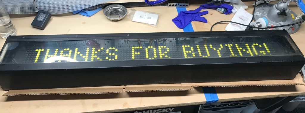
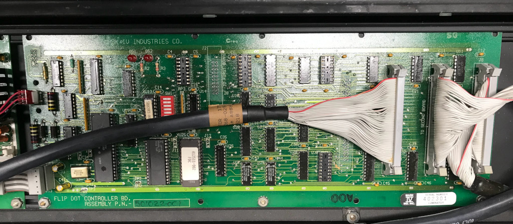
Here’s the sign as purchased from ebay seller orionii951 (very happy with them and the other eBay folks I worked with on this project). The sign is a Luminator GTI MAX 7×90 Flip Dot display. To attempt to date it, the power supply board that came with it is dated March 1992, so call it close to 30 years old. This type of sign was designed to be on the front or side of something like a train or bus. It might display the next stop or the route, like “21 New Milford” but could update as the vehicle changed routes. The system is 4 parts. A master controller for the vehicle (which I will replace with a Raspberry Pi), a PC board for controlling the sign, three 7 pixel by 30 pixel flip dot elements, and a power supply converter.
After finishing up a couple of other projects, I finally cracked the package open and applied some power to see if I could make something from this.
As I learned later, this was not the complete power on test, but it looked good to me at that moment. I spent the next 48 hours or so working on the communications to the sign and trying to get messages to display.
Sign Communications – Part 1
One of the things I was extending my skills on with this project was the use of RS485 communications. I floundered around with a few attempts to communicate with the sign, but I couldn’t really determine if the issue was with the sign or my software.
I turned to a software program I found on eBay that was just what I needed. Not only did the windows based Luminator and NXTP Transit Bus Destination Sign Control Program give me a known working tool to continue my attempts, it has a massive 194 page manual which really took me to school on what I needed to know. After multiple tests of dongles and scans and polarities, I determined there was a hardware problem with the sign more than a software or interface problem.
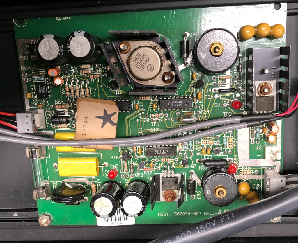
Putting the board on the bench, I tested voltage on the controller board from the existing power supply and found the output very low. The controller board ran on 12V and 5V, so I was quickly able to bring in replacement from another project that was known good.
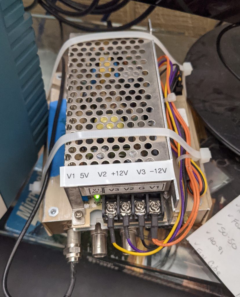
I connected the power supply up, checked the voltages on the controller board and determined the voltage was right on where it should be. Powered down, connected up the displays and set it to self test. GREAT NEWS! This self test is going way further than it made it before. BAD NEWS! After 2 passes the controller board let the magic smoke out.
My next step was to attempt to repair the board. After I chatted with Eric who wrote the Luminator software, I also ordered a couple of replacement comm chips as he mentioned voltage problems have impacted them in his experience. Long story short, parts come in a few days later, the board lights up but it doesn’t fix the comm problem. I order a replacement board from eBay and wait 14 days for 2 day USPS shipping to arrive.
While I’m waiting, I’ll build a box
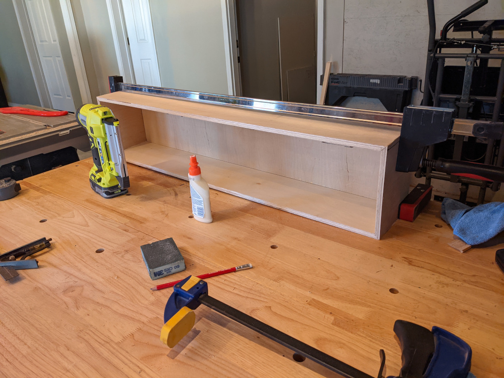
Having watched a lot of Adam Savage Tested.com videos recently, I was sure I could build a better container for the sign than the original metal and plexiglass model. For one thing, I didn’t need to mount this to a bus any time soon. For another, I knew I needed room for the new power supply and the Raspberry Pi control that would eventually drive this. Finally, I wanted a way to add some LED light to brighten up the sign, so I needed room for that. Note the sign had the option of coming with a fluorescent light, but I opted out of that, because it would just get damaged in shipping and I didn’t need it anyway.
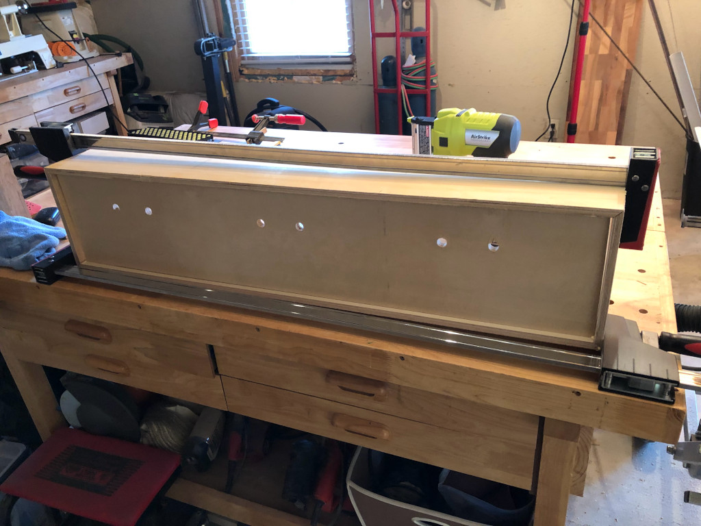
Huge shout out to my friend Karen who let me play around in her basement workshop one day while she slaved away on conference calls. She had a table saw and all the right clamps I needed to build a frame from half-inch plywood. I also created a middle mounting board, one side holds the dot displays and the other the electronics. Those circles will be routed out to let the control cable connectors pass through.
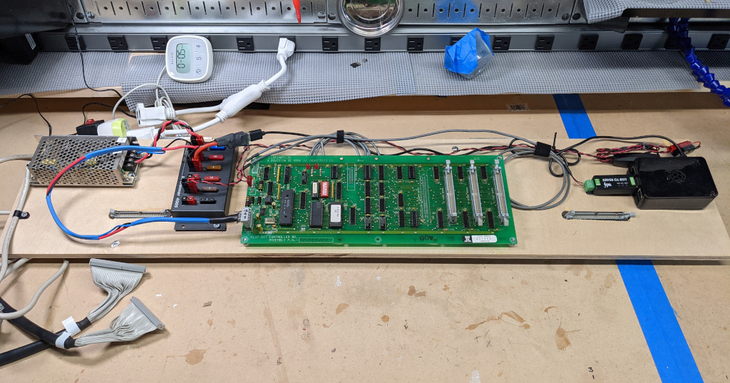
In the image above you can see the layout of the back of the display. From left to right as you look at it (will be right to left when mounted) there is:
– Power Supply converting 120V to 12V and 5V
– RigRunner 4005 12V Anderson PowerPole fuse block for distribution
– Luminator MAX Controller Board
– Raspberry Pi Model 3B with Waveshare USB to RS485 device.
– 12V switch for powering the LED lights to illuminate the sign (not shown).
Why is the Pi running from a 12V to 5V converter instead of the 5V from the PS? I get the benefit of fusing the Pi and I remove the risk of causing any power drops to the board from sharing a 5V bus.
I could have kept it natural, but I decided to paint the box white. You can see a small rail inside for the mounting board to rest against and offset the sign into the box. Two small pieces of trim clean up the look and allow for a spot to mount a 12V strip of LED lights to brighten the display.
It’s Alive!
So the waiting was over, the US Post Office delivered their 2 day package only 12 days late and I had the new controller board. Thanks to eBay seller Second Wind Surplus. All that was left was to connect it up and start testing.
If you watched the video you can see the controller board was successful its first time out. The reason some dots (pixels) were not changing was due to lose connections of the serial cables between the display section and the controller board.
The next step was to repair the remaining 8MM sized pixels that has been just physically stuck because of moving around or had become unseated. I’m doing this later in the video, a pair of tweezers worked well to allow me to grab the element and reseat it.
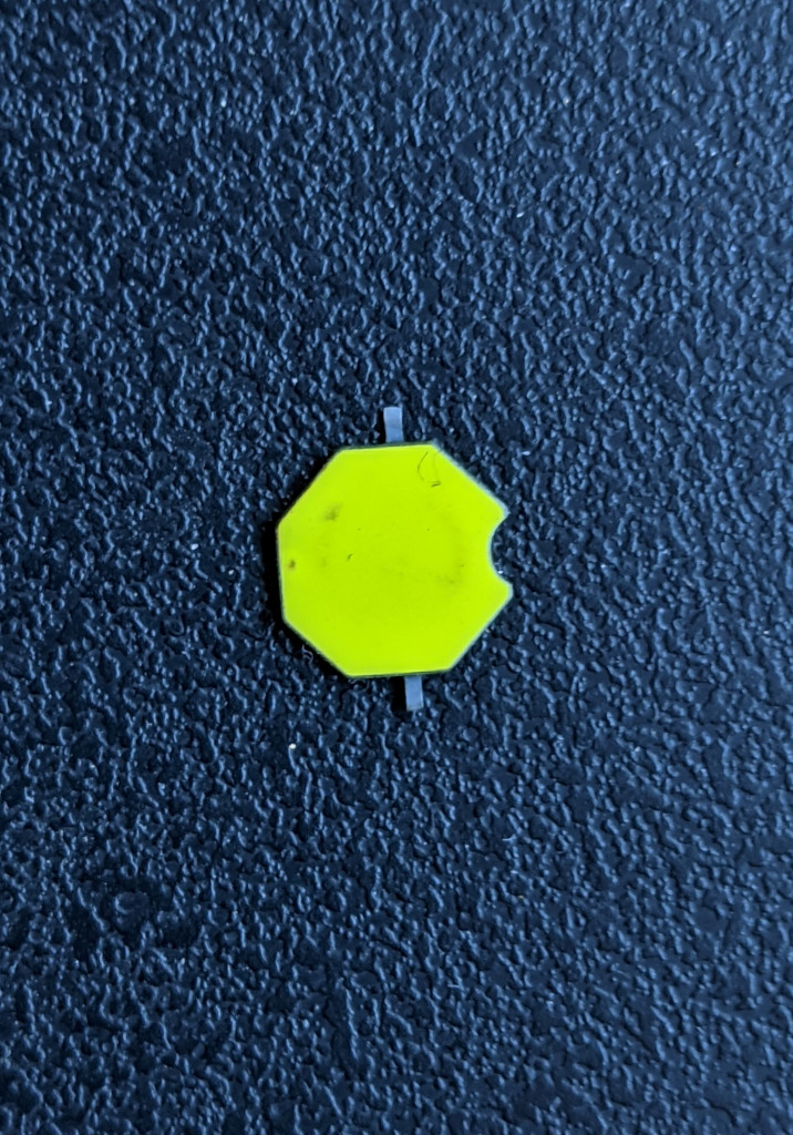
Through the entire project, about 5 weeks of on and off work, I did manage to lose one dot (from the right 4th row, 3rd down). It’s the little element (picture above) that is lost, I replaced it with the one at the bottom right corner to make things look a little less obvious. I’ll be poking around to try and make this complete.
Time to Play
I connected up the Windows Luminator Software and I was able to display virtually anything I could think of. That software is very powerful and for $25 bucks quite the bargain for me. Here are a couple of videos with messages.
OK, let’s wrap it up.
With everything working I mounted the board inside the sign shell. Here’s one last peek at the back with everything inside the board.
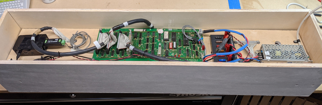
One piece of troubleshooting here. The 12V to 5V element I was using in the earlier picture wasn’t sustaining enough voltage to run the Pi consistently, so I swapped it for another I had that performed up to 2.3 amps. The only other change was I ran the 120V power cord through a hole in the bottom of the box to make it a little tidier.
After some bench testing, I confirmed I was able to send data to the sign via the RS485 dongle on the Raspberry Pi. I don’t have any formal programming language, but I seem to be gravitating to Python more than anything else. I browsed the web for some repositories and found a starting point I could modify things from. The Python code below allowed me to dump a message (data_x lines) created by the Windows Luminator program to the serial output like this:
import time
import serial

check_addr=":010003040FE9\r\n"
do_init=":01000302FFFB\r\n"
idle_reset1=":010003059364\r\n"
idle_reset2=":01000303A752\r\n"
idle_reset3=":0100030200FA\r\n"
config_data0=":01000303A158\r\n"
config_data1=":1000000004200006071E1E1E00080000000000005D\r\n"
config_data2=":00000101FE\r\n"
rcv_data=":01000303A257\r\n"
data_1=":10000000010A00007F7F7F7F7F7F7F7F7F7F7F7FF1\r\n"
data_2=":100010007F7F7F7F7F7F7F7F7F7F7F7F7F7F7F7FF0\r\n"
data_3=":100020007F7F7F7F7F7F7F7F7F7F7F7F7F7F7FFF60\r\n"
data_4=":10003000FFFF7F7F7F7F7F7F7F7F7F7F7F7F7F7FD0\r\n"
data_5=":100040007F7F7F7F7F7F7F7F7F7F7F7F7F7F7F7FC0\r\n"
data_6=":100050007F7F7F7F7F7F7F7F7F7F7F7F7F7F00109E\r\n"
close_1=":00000601F9\r\n"
close_2=":01000306FFF7\r\n"
close_3=":0100030200FA\r\n"


with serial.Serial("/dev/ttyUSB0", 19200) as srl:

    srl.write(check_addr)
    print"Check Address"
    time.sleep(1.0)

    srl.write(do_init)
    print"doInit"
    time.sleep(1.0)

    srl.write(idle_reset1)
    time.sleep(0.3)
    srl.write(idle_reset2)
    time.sleep(0.3)
    srl.write(idle_reset3)
    print"IdleReset"
    time.sleep(1.0)

    srl.write(config_data0)
    time.sleep(0.3)
    srl.write(config_data1)
    time.sleep(0.3)
    srl.write(config_data2)
    print"Config Data"
    time.sleep(1.0)

    srl.write(rcv_data)
    print"Recv Data"
    time.sleep(1.0)

    srl.write(data_1)
    time.sleep(0.3)
    srl.write(data_2)
    time.sleep(0.3)
    srl.write(data_3)
    time.sleep(0.3)
    srl.write(data_4)
    time.sleep(0.3)
    srl.write(data_5)
    time.sleep(0.3)
    srl.write(data_6)
    print"Write Data"
    time.sleep(3.0)

    srl.write(close_1)
    time.sleep(0.3)
    srl.write(close_2)
    time.sleep(0.3)
    srl.write(close_3)
    print"Close"
    time.sleep(1.0)
A note on sending the data. This board is very sensitive to how quickly it gets the data sent, and I did not create any code here to wait for acknowledgement. That’s why I used a lot of short “time.sleep(x)” options. By just changing the “data_X” information I could send different messages, which allowed me to rotate between “All On”, “All Blank” and the “Game Over” message for testing. This also allowed me to test these as an unmonitored CRON execution which worked without issues.
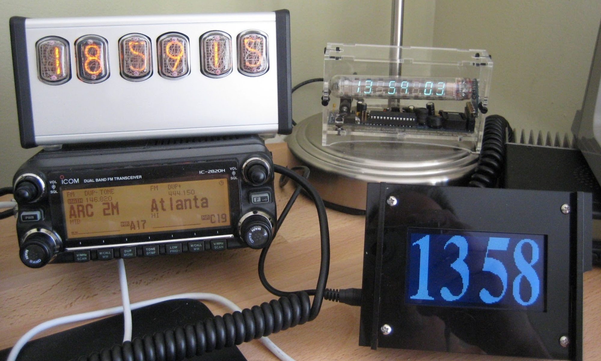
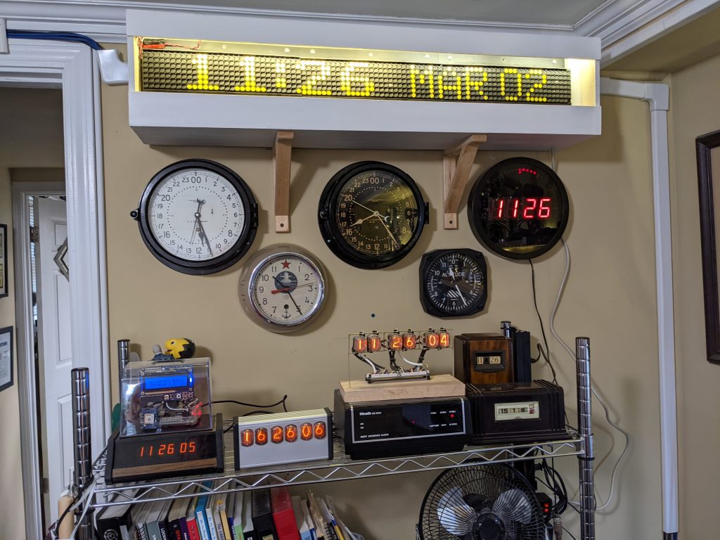
So, now that I am comfortable writing data to the sign with the Pi, decided it was time to mount the display in my office along with my other clocks. It took me about an hour to get things the way I wanted them. Here’s a 5 minute time lapse, which I left a little long in case anyone wanted to pause. The sign box sits on 2 Ikea L-Brackets mounted into the studs amd are secured with 2 screws from the bracket into the plywood bottom. Just unplug and unscrew these two screws to take down for work.
The actual size of the sign box ended up being 39″ wide, 8.5″ high and 7″ deep. I could have made the box maybe half-an-inch smaller in all directions, but space was not an issue. It intentionally sits proud of the wall to allow for circulation. The L-brackets have a small lip and the top sits against the plastic wire track which holds low voltage control cables.
Status check: Device running, box build, sign mounted, communicating with the Pi. So it’s clock time! I had my eye on the dotclock program on GitHub which had been written for the next generation of Luminator signs (mine is a MAX, this is written for a MAX 3000). I had not used the Rust compiler before so this took me a bit to understand, but I figured it out after a few minutes. Top tip, using apt-get did not get me the latest version, which the dotclock program didn’t like. Instead, I used the Rust-Lang.org site and that did the trick.
The dotclock program is “run-once and terminate” code. In order to get the time to change, I set the code to run via CRON every 5 minutes at first as a shake down and it did great. Once I passed 12 hours with no obvious errors at the 5 minute pace, I fancied it up a little to update every minute.
I thought it would be fun to change the way the display shows on alternating minutes. That is accomplished with these nifty 2 line entries in crontab. (Thanks Internet!) The -t setting tells it to display time in 24 hour mode, so it alternates between that and AM/PM view every other minute.
*/2 * * * * /home/pi/dotclock/target/debug/dotclock -t /dev/ttyUSB0 &>> /home/pi/dotcron.log
1-59/2 * * * * /home/pi/dotclock/target/debug/dotclock /dev/ttyUSB0 &>> /home/pi/dotcron.log
The Happy Recap
Project goal achieved. I have a lovely clock addition to my collection. The Flip Dot Clock keeps time to within 1 second or so consistently. It’s nice to listen to it tick every minute. For extra nerd points, it combines well with the Big Ben Chimes I have on the quarter hour running on another Pi.
This project stretched me in a number of ways. I’m not used to working on a single item off and on for 6 weeks, so that was interesting. I have built a few boxes for things, but this felt like a better, sturdier, higher quality build for me. I did not know a thing about RS485 or the Luminator protocol before starting this, but I get it now. I feel more confident in my electronics troubleshooting and repair, even though I did end up having to buy another board. All good things!
What’s Next?
I won’t say this is the final version, but a great stopping point for sharing. I plan on adding small messages on the display at 10 minute intervals. One might pull in my YouTube subscriber stats for my N4BFR Vision channel. Another might give me the weather, or the solar weather for DX. How about a breaking news alert? I need to get some more understanding of another GitHub repo for FlipDot. I also might set up something to take messages from online like FlippyFlipDot. It’s good to have a basic platform to build on.
Thanks for reading this far. If you have questions, please reach out on my social media channels.
Reddit: u/N4BFR
Twitter: @N4BFRVision
Facebook: https://www.facebook.com/N4BFRVision
YouTube: N4BFRVision Channel