In previous blog installments, I’ve tracked how long it takes for my computer to calculate an extended number of digits of Pi as a performance metric. I called it How Long for Long Pi. There is a new computer to rule the ham shack today. It’s a Mac Mini M4 Pro with 48 GB of RAM. I decided to compare it to my most recent machine tests and see how it does.
I broke out my Python script from last time and started doing test runs. Let’s do a basic comparison to my I7 12th Gen PC with 32 GB of RAM. Those were the top performers in my previous experiment.
Machine (Times are 3 run avg)
Pi to 100K
Pi to 1M
Notes
i7 Desktop with Win 11 12700A CPU
6.2 Sec
12 Min 35.0 Sec
i7 Desktop with Ubuntu 12700A CPU
5.4 Sec
08 Min 57.2 Sec
Mac Mini M4 Pro
4.47 Sec
07 Min 27.0 Sec
Executed with Py Editor from Apple App Store
By this benchmark alone, the new Mac Mini M4 Pro is processing at 16.7% faster than a 2022 generation Intel desktop running Linux. How about 40.8% better than Win 11?
I’ll add some general observations. The Mini doesn’t seem like it’s breaking a sweat. It’s warm to the touch but not overly so. The fan has not come on. I’m typing this blog post while the calculations are happening, so it’s even got a little bit of a handicap.
I did have to make one change to the code, adding a line to allow for a larger string. The version I used is below. Let me know on my socials if you try this.
#-*- coding: utf-8 -*-
# Author: Fatih Mert Doğancan
# Date: 02.12.2014
# Timer Integration and string modification 0-Nov-2024 by Jim Reed
# Timer function Start
import time
start = time.time()
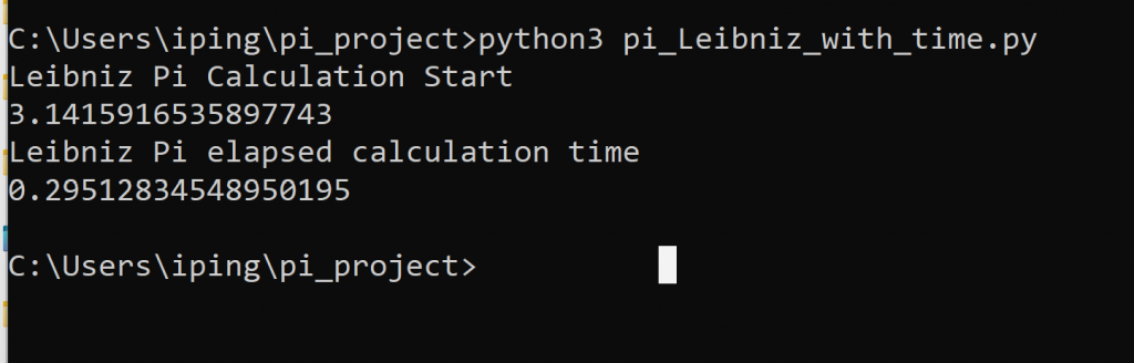
print("Dogancan - Machin 1,000,000 Digits Pi Calculation Start")
#Original Calculation Code goes here
sys.set_int_max_str_digits(1100000)
def arccot(x, u):
sum = ussu = u // x
n = 3
sign = -1
while 1:
ussu = ussu // (x*x)
term = ussu // n
if not term:
break
sum += sign * term
sign = -sign
n += 2
return sum
def pi(basamak):
u = 10**(basamak+10)
pi = 4 * (4*arccot(5,u) - arccot(239,u))
return pi // 10**10
if __name__ == "__main__":
print (pi(1000000)) # 10000
# calculation code code ends
# timer reports
end = time.time()
print("Dogancan - Machin 1,000,000 digits elapsed calculation time")
print(end-start)
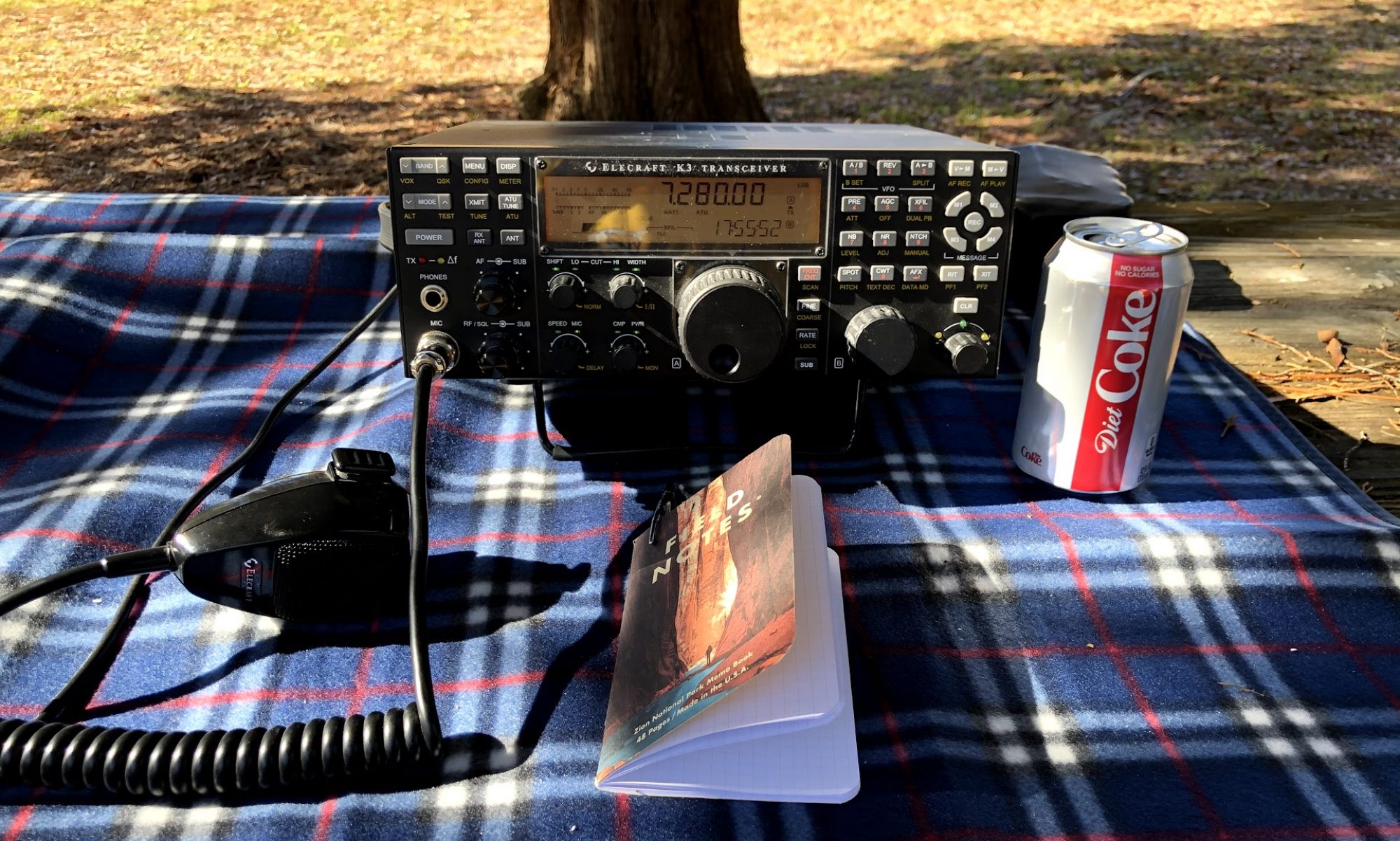
What’s a better receiver for an APRS receiver for packets from the ISS? Let’s do a side by side test.
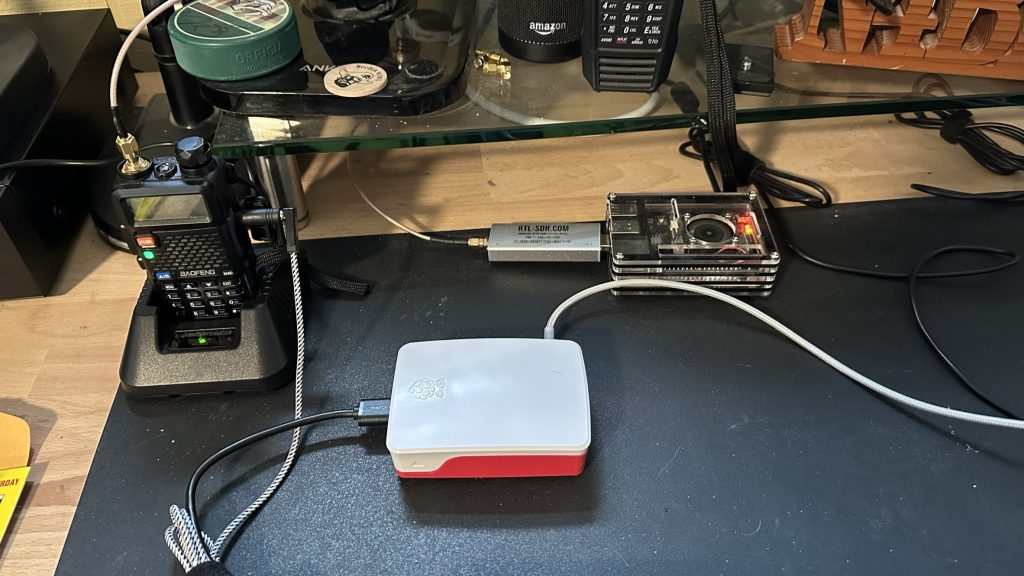
Left is the challenger Baofeng, Right is the RTL-SDR Champion
For several months now, I have been running signals from a discone antenna on my roof into a RTL/SDR receiver connected to a Raspberry Pi. On a good day, I pick up a few packets from the ARISS digipeater running on the ISS at 145.825 MHz.
I was wondering if I could hear more packets with a different receiver so I decided to create a side/-by-side A/B test. Here’s the configuration:
Discone Antenna fed into my “Tech Center” / Ham Shack Split antenna with a coax “T” – one goes to champion setup, one to challenger. Using equal length coax with SMA connectors.
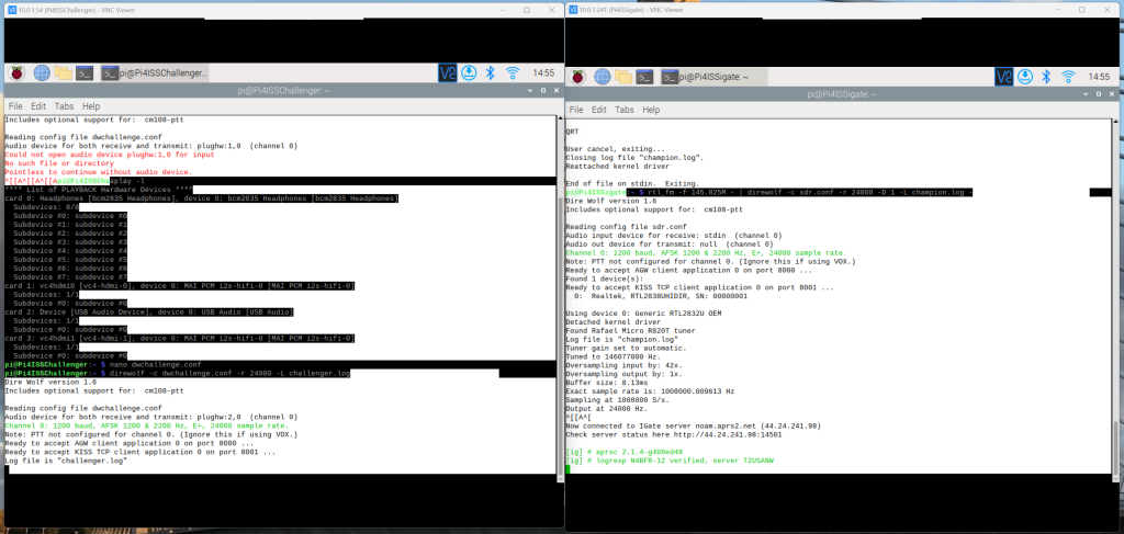
Both are tuned as best I can for audio quality using data on 144.390, and then switched to the ISS frequency.
The experiment was configured on Wednesday, December 21 in anticipation of a predicted 83 Degree Elevation pass on 22-Dec-22 at 17:26 UTC. I’ll update this blog as I get pass data in.
Update: 23-Dec-22 at 0955 UTC – A moderate height ISS pass (32 deg El) coming through this morning at 1007 UTC. Couldn’t gather data Wednesday because the ISS radios were off for the space walk.
Update: 23-Dec-22 at 1023 UTC – ISS radios were still off during the pass. Trying again later today (Friday).
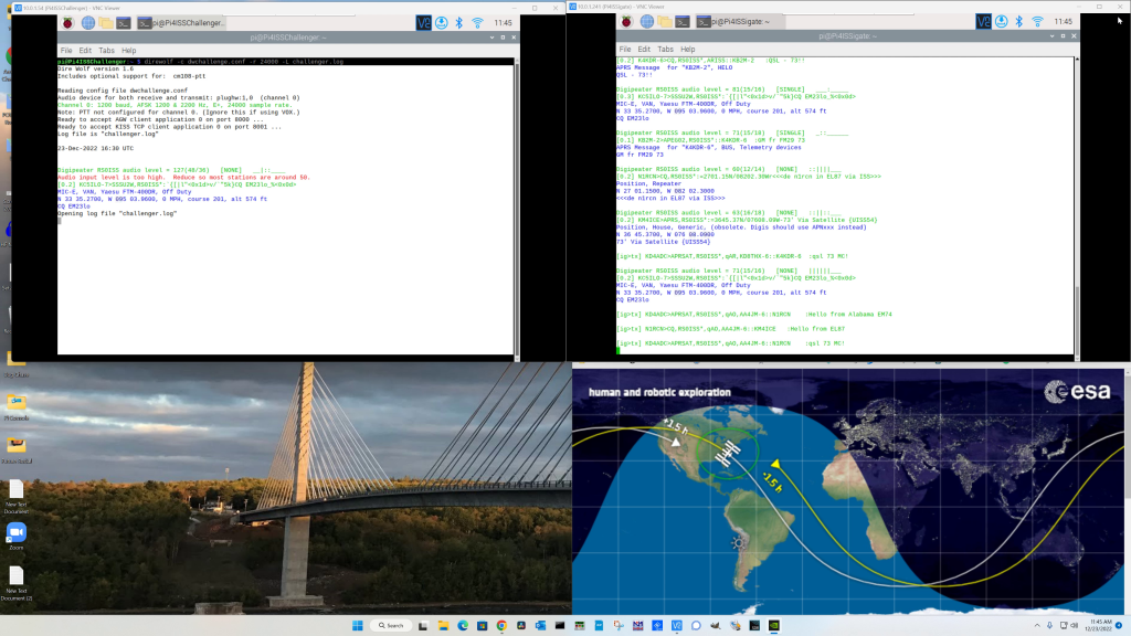
Challenger radio on left, champion SDR on the right.
Update: 23-Dec-22 at 17:00 UTC – Good pass with many packets caught. There was an obvious winner in the SDR. You can see on the screen show it captured many packets while the Baofeng only reported 1 for the entire pass. Going to change HT’s and try again on a later pass.
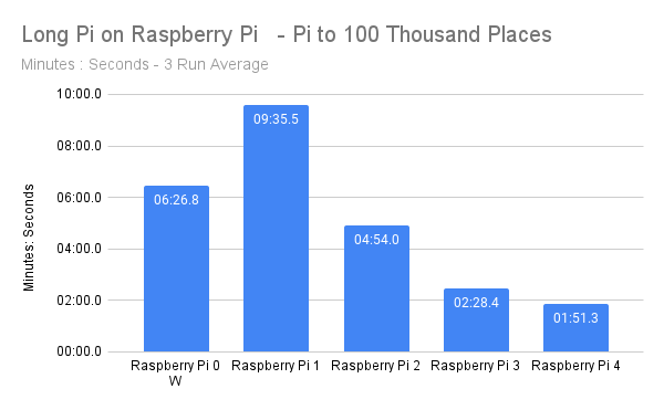
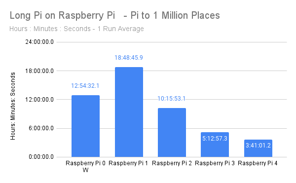
In the 4th post in this series (find post 3 with Win-tel stats here) I broke out the Raspberry Pi collection to see how this device has changes over the generations. I can say for sure it only gets better.
In 4 generations the Pi performance has improved from almost 19 hours to calculate Pi to 1 Million Places to just under 4 hours. That’s a 80% performance improvement in 8 years. Now the price has gone up, the Pi 4 as I have it was $75 vs the $25 of the Pi 1, but 4 times faster for less 3 times the price over those same 8 years is amazing to me.
I take the Pi 0 W results with a grain of salt because that’s supposed to be a smaller, less powerful board. But it costs $10 new. If you want to compare them by their different SOC’s Wikipedia has a great article that has all the specs.
I’m still a big Raspberry Pi fan and I probably could do more with a single Pi than I do, but I have a dozen in this room and they just crank along like magic. I don’t have one favorite project but one that you might want to read about is my Flip Dot Clock.
Today I have some older Apple machines on the bench. I’ll share those results tomorrow.
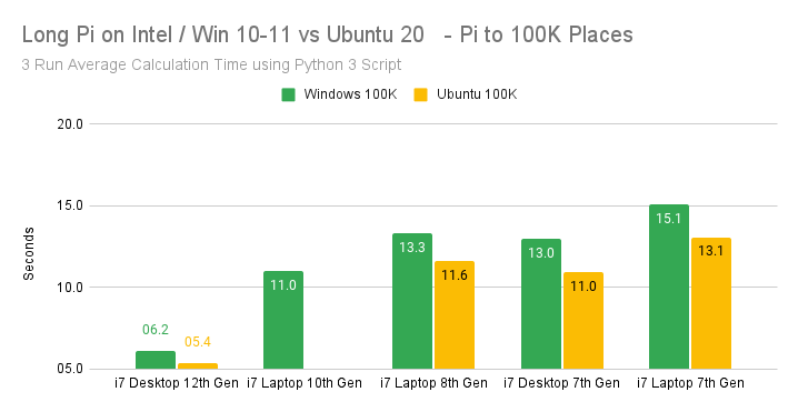
Following up on my How Long for Long Pi posts from Thursday and Friday I wanted to start quantifying the data a little more. I was able to gather data from 5 Intel computers. They are:
CPU Type
CPU Generation
Form Factor
Intel i7
12th Generation
Homebuilt Desktop
Intel i7
10th Generation
Legion Laptop
Intel i7
8th Generation
Yoga Laptop
Intel i7
7th Generation
Asus ROG Desktop
Intel i7
7th Generation
Yoga Laptop
My testing methodology was to run 3 passes of the test calculating Pi to 100,000 places via a Python 3 script (see Friday’s post) and then to 1,000,000 places. All 5 machines ran native Windows. (The Legion Laptop and 7th Gen Yoga are Win 10, the others Windows 11). On 4 of those machines I could dual boot into Ubuntu 20 Linux from a USB SSD drive.
I was surprised that the Ubuntu versions averaged 13.7% faster calculation time than the Windows machines. I don’t have the details to drill down further to attribute that to the overhead of the operating system or to efficiency of the versions of Python 3.10 or just something else entirely.
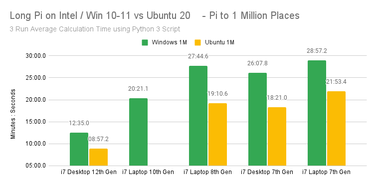
When you spend more time calculating, you find an even bigger difference in times. Ubuntu calculations were 28.3% faster at this length of calculation. The other thing that jumped out at me in both calculations was that a 7th Gen Desktop was faster than an 8th Gen Laptop (4.3% on Ubuntu 1 Million) While all these processors are multi-core, it appeared to me that all these were running in a single processor while calculating, using Task Manager on Windows and htop on Ubuntu.
Testing of all 5 versions of Raspberry Pi (0W, 1, 2, 3, 4) are underway. I’ve also got some other devices to test, and I was surprised to see a handheld device outperform one of the 7th Gen Intel machines at a Million places.
Again, please feel free to provide comments on my Twitter – @N4BFR.
Note: This is less of a blog post and more of a running commentary on a project I have conceived. I have a long way to go on it but I hope you enjoy the journey.
I’ve been thinking about computers I have seen at places like The National Museum of Computing in the UK or the Computer Museum of America here in Metro-Atlanta. One of the things that has always challenged me is how to benchmark computers against each other. For instance, we know the Cray 1A at the CMoA had 160 Megaflops of computing power, while a Raspberry Pi 4 has 13,500 Megaflops of computing power according to the University of Maine. What can you do with a megaflop of power however? How does that translate in the real world.
I’m considering a calculation matrix that would use one of two metrics. For older computers, how many places of Pi can they calculate in X amount of time. Say 100 seconds? For newer computers, how long does it take for the machine to calculate Pi to 16 Million places. Here are my early examples:
Pi to 10,000 Places on Raspberry Pi
Computer
Processor
RAM
Elapsed Time
How Calculated
Raspberry Pi Model 3
ARM Something
Something
6 Min 34 Sec 394 Seconds
BC #1 (Raspbian)
Raspberry Pi Model 3
ARM Something
Something
2 Min 15 Sec 135 Seconds
BC #2 (Raspbian)
Raspberry Pi Model 3
ARM Something
0 Min 0.1 Sec
Pi command
Pi to 16,000,000 Places
Computer
Processor
RAM
Pi to 16M Places Time
How Calculated
Lenovo Yoga 920
Intel Core i7-8550U CPU @ 1.8 GHz
16 GB
9 Min 55 Sec 595 Seconds
SuperPi for Windows Version 1.1
Lenovo Yoga 920
Intel Core i7-8550U CPU @ 1.8 GHz
16 GB
0 Min 23 Sec
Pi command
N4BFR Vision Desktop
Intel Core i7-12700K CPU @ 3.6 GHz
32 GB
3 Min 15 Sec 195 Seconds
SuperPi for Windows Version 1.1
Raspberry Pi Model 3B+
ARM 7 Rev 4 (V71)
1 GB
6 Min 03 Sec 363 Seconds
Pi command
Tools I am considering to use will be an issue because I want consistent performance across operating systems. Efficiency will be an issue because I will want something that computes at roughly the same speed for windows as for Unix.
SuperPi for Windows 1.1 was the first I came across and it seemed to be pretty straightforward that would run on many versions of Windows I came across.
Moving on to a calculator I could use in Unix, I found this John Cook Consulting Website that had a couple of calculations using the BC program. I found the results inconsistent on the Lenovo Yoga 920
BC Calculation 1: time bc -l <<< "scale=10000;4*a(1)"

BC Calculation 2: time bc -l <<< "scale=10000;16*a(1/5) - 4*a(1/239)"
I then found the Pi command on pi that might be more consistent with what I need.
$ time pi 10000
Pi Calculations on Lenovo Yoga 920 Windows time is reported by SuperPi. BC time is “Real” time reported by process.
Pi Calculated to X Places. X=
Windows Time
BC `
BC 2
Pi Command
10K (Pi Compairison)
1 Min 45 Sec
0 Min 32 Sec 0 Min 35 Sec
0.09 Sec
20 K
3 Min 22 Sec
0.
50K
Incomplete after 15 minutes
128K
0 Min 01 Sec
Incomplete after 60 Minutes
512K
0 Min 08 Sec
1 M
0 Min 16 Sec
8 M
3 Min 05 Sec
16 M
9 Min 55 Sec
0 Min 23 Sec
So using BC as a method of calculating does not seem to scale.
Coming back to this a few days later, I may have a partial solution. This will limit the use of this on older machines, but should be fairly consistent with newer ones. I plan to do the calculation with a script in Python 3. This should allow for roughly similar performance on the same machine to make results more comperable.
Python3 methods for calculating Pi: https://www.geeksforgeeks.org/calculate-pi-with-python/
I was able to get a rudimentary calculation in Windows using both of the formulas and include a function to time the process consistently. Now I need to compare in Linux and blow out the calculation to allow a material number of places for this to be an effective measure.
I have found a few more options thanks to StackOverflow and I’m testing them now on my 12th Gen Intel machine.
100,000 digits of Pi using the “much faster” method proposed by Alex Harvey: 177.92 seconds for the first pass, 177.83 seconds for the second pass. I like the consistency
Guest007 proposed an implementation using the Decimal library. I attempted a 10,000 digit calculation and that took 24.6 seconds, 100,000 places didn’t complete after more than 10 minutes. Interestingly, a peek at the system processing said it was only running 8.1% of CPU time.
Tomorrow I’ll start a new chart comparing these two methods across multiple machines.
I’m into accurate time. Ever since I stumbled across the SatSignal.eu site I have been running a Raspberry Pi on my network as a Stratum 1 time server. For those not familiar with the stratum, the only level higher is Stratum 0 and that is reserved for the absolute standard of time sources like the National Institute of Technology clock and GPS Satellites.
2016 Raspberry Pi Clock showing leap second addition at the end of 2016
I had been having some entropy on my current set of 6 GPS clocks from various issues, so I decided to rebuild my clock from the base install of the new Raspbian Bullseye distribution. Since I didn’t see a single definitive source, I put this listing together and I’m glad to share it with the community because it has been good to me with previous builds. My sources include SatSignal.eu, tomasgreno.cz, and adafruit.com. Much of what I did is just compiling and changing the order of some steps slightly to minimize reboots. Those others may work better for you, but this version worked for me.
Let’s talk hardware. I have done this project with a Raspberry Pi 1 through a Pi 4 as well as the Pi Zero and Zero W. I prefer the form factor of the full sized Pi to go along with the GPS hardware, but as long as you can make the GPIO connections from the GPS to the Pi all should work.
For a GPS module I use the Adafruit Ultimate GPS with the following pin connections. If you want to use something different, consult the breakout manufacturer and use pinout.xyz to set the proper connections. For my connections I typically use:
GPS Breakout Pin
Raspberry Pi Pin
VIN (Voltage in)
Pin 4 – 5V Power
GND (Ground)
Pin 6 – Ground
RX (Receive, to get data from the Pi TX)
Pin 8 – GPIO 14 – UART TX
TX (Transmit, to send data to the Pi RX)
Pin 10 – GPIO 16 – UART RX
PPS (Pulse Per Second)
Pin 12 – GPIO 18
It’s not a typo, make sure TX goes to RX on the other board and vice versa.
Now on to software. Start with a clean version of Raspbian Bullseye on an MicroSD. I downloaded mine from the official RaspberryPi .com website. I used the “Raspberry Pi OS with Desktop” version and used an 8 GB MicroSD card as the media. I’m skipping the items related to base configuration of the host name and other start-up items, there are other sources for that. All the commands you see will be via the command prompt.
The instructions from here forward assume you have a working Raspberry Pi, connected to the internet with the GPS attached.
Start by adding two additional lines to the /boot/config.txt file. This starts the process to disable Bluetooth on the Pi and sets the Pulse Per Second GPIO Pin if your GPS supports it.
Note in this document, the command following $ gets entered at the command prompt, other commands are entered inside the file, at the bottom on a new line is usually good. Once commands are entered, use Ctrl-X, Y and Enter to save and exit the file and return to the command prompt. And yes, I use NANO as my text editor. You should use what you want. I’m not a text editor drill sergeant.
$ sudo nano /boot/config.txt

#Changes for GPS Clock
dtoverlay=pi3-miniuart-bt
dtoverlay=pps-gpio,gpiopin=18 (Customize to appropriate pin)
Disable Bluetooth in system control
$ sudo systemctl disable hciuart
Add a reference to /etc/modules to software for PPS management we will install shortly.
Now let’s test to see if the PPS software was installed by checking some OS boot logs
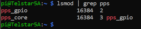
$ lsmod | grep pps
You should get two responses back that look something like this. Don’t worry if the numbers are different.
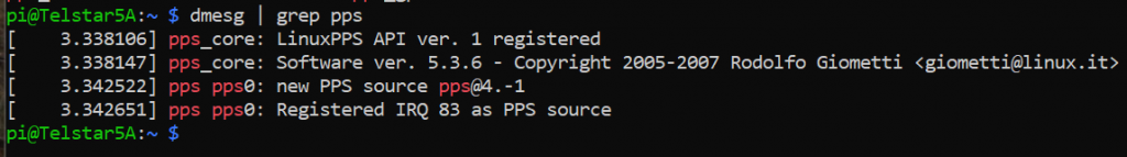
$ dmesg | grep pps
Make sure you have a line that says “new PPS source…”
Once you see both of those, we can check and see if the GPS is sending data. Your GPS must have a “fix” which means it’s getting data from at least three satellites in order for this to work.
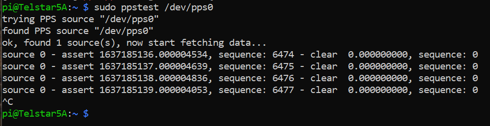
$ sudo ppstest /dev/pps0
Success looks like this:
Don’t worry about the specific numbers, just look for incrementing sequence numbers. The data will continue to populate every second until you hit CTRL-C to stop it.
Moving on, we have installed the GPS module and gotten data from part of it, but have not installed the main GPS software set yet. This should do it:
Again, CTRL-C to stop it. If you get a stream of data and it’s gibberish your GPS may be sending at a different rate. A good place to start if you see that is this SatSignal.eu page which looks at other GPS modules and other methods.
Now, let’s temporarily send that data to some GPS software for interpretation.
$ sudo gpsd /dev/ttyAMA0 -n -F /var/run/gpsd.sock
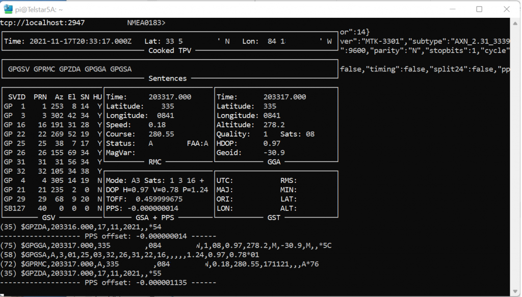
Then we’ll open the GPSMON software to look. (There’s also a tool called CGPS. Use either, this is a personal preference thing)
$ gpsmon
Location obscured for privacy.
The screenshot above will tell you your exact position, the number of satellites your GPS sees, and the status of your PPS data all in one screen. Did I mention you CTRL-C to get out of a screen like this? Because you do.
Configure the GPS software to auto-start when you boot your machine. I have seen a couple of different processes, but this one works consistently for me.
$ sudo nano /etc/default/gpsd
Unlike the other file edits where you add a line, this is what the whole file should look like when you are done. You may just want to cut and paste this whole section, or type it in, whatever works for you, I won’t judge.
#Updated for GPS Pi Clock

START_DAEMON="true"

# Devices gpsd should collect to at boot time.

GPSD_SOCKET="/var/run/gpsd.sock"

# They need to be read/writeable, either by user gpsd or the group dialout.
DEVICES="/dev/ttyAMA0"

# Other options you want to pass to gpsd
GPSD_OPTIONS="-n"
GPSD_SOCKET="/var/run/gpsd.sock"

# Automatically hot add/remove USB GPS devices via gpsdctl
USBAUTO="false"
Almost done with the GPS section. Four more commands to go.
That third $ command (between “disable” and “reboot” goes on a single line, this blog text tool wraps it. It should look like this:
If you want to reconfirm everything is working again after reboot, run GPSMON like above and look at the pretty data fly by. Now let’s connect the GPS to the clock. I’m choosing to use NTP as my time server software for this project. You might want to play with Chrony as well.
$ sudo apt-get install ntp
Once that is done, you want to stop the timesyncd service that is installed by default with Bullseye and replace it with NTP.
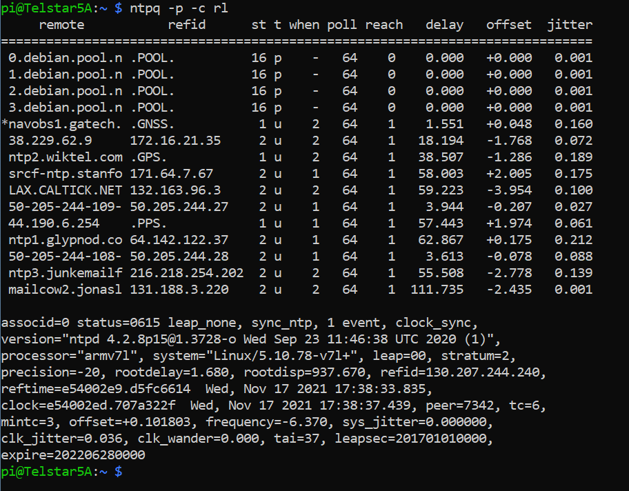
Let’s test. “Out of the box” the NTP software checks with servers on the internet to get the time. It will look something like this:
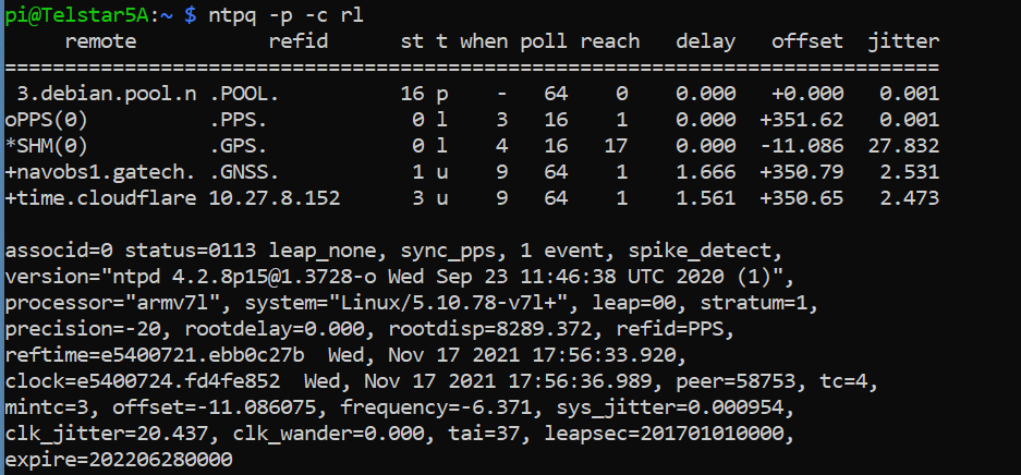
$ ntpq -p -c rl
The * on the left indicates the chosen server, this one is at Georgia Tech.
Great news! Clock is syncing, but if you look at the bottom you’ll see after “leap=00” it says “stratum=2” which is nice, but we want to use the GPS to make it a Stratum 1 clock.
It’s time to cross the streams and point the NTP software to look at the GPS and PPS signals for time. That means editing the NTP configuration file.
$ sudo nano /etc/ntp.conf
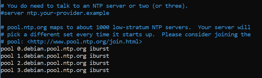
There are a lot of other settings in the file, so I won’t give the whole file this time but here’s what I recommend. Scroll down until you get to this section:
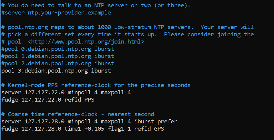
Use the # sign as the beginning of a line to comment out several of those “debian.pool” lines. You do want to keep an internet server on the list as a backup and for diversity, but you won’t need all of them. Save that for the folks that don’t have satellite time at home. Just below the “pool” entries, add each of the 6 lines on a new line:
# Kernel-mode PPS reference-clock for the precise seconds
server 127.127.22.0 minpoll 4 maxpoll 4
fudge 127.127.22.0 refid PPS

# Coarse time reference-clock - nearest second
server 127.127.28.0 minpoll 4 maxpoll 4 iburst prefer
fudge 127.127.28.0 time1 +0.105 flag1 1 refid GPS
If you want to use different servers on the internet, there are plenty to supplement. The manual page about ntp.conf can tell you more about other things you can do with this file.
When your changes are made it should look like this.
Do that cool CTRL-X thing and get out of there before you break anything (kidding).
Time to get the NTP client to read the new configuration file.
$ sudo service ntp restart
It sometimes helps to reboot too. Your call. Now let’s check and see what time source we are using:
$ ntpq -p -c rl
Success! Why? Three things you want to see on this screen: 1 – The SHM / .GPS. line has a * next to it, indicating it’s the primary time source. In the “st” column you can see a 0 which indicates it’s connected to a “Stratum 0” source. 2 – The PPS / .PPS. line has an o next to it, indicating it is a “PPS peer” and it’s getting very specific pulse data from the GPS signal. It’s also a “Stratum 0” source. 3 – The “stratum” field for your NTP server now is “stratum=1” which is pretty much the best you can get as a home user.
It may take a little bit for the PPS to settle in as the primary time source, so don’t worry if it doesn’t do it in the first 5 minutes.
So, that’s the project. Why do you need this? Well, I do it for fun, but there are several applications that require very accurate time. For instance in Ham Radio the cycles for a program like FT8 depend on an accurate clock to switch between receive and send modes. Is this the thing I’m going to replace a Rubidium time standard with? No, but for about $100 bucks it’s a nice thing to have an a good early project for someone learning about Raspberry Pi. You can set Windows, Mac or Linux clients to point to your home server for time instead of time.windows.com or other sources.
One final note, this is accurate for me as of the time in that last screen shot. Something is bound to change eventually, so expect these instructions to drift over time as things change. Figuring that out is one of the fun things for me.
If you do this project and want to share success, you can tweet me @N4BFR or find me in other place on the internet.
I started upgrading one of my Raspberry Pi from Buster to Bullseye by using the APT tool and following along with the TomsHardware Guide. After completing Step 6 by changing the repository name, I ran
$ sudo apt dist-upgrade
It ran a couple of items then this advisory appeared.
Some packages could not be installed. This may mean that you have
requested an impossible situation or if you are using the unstable

distribution that some required packages have not yet been created

or been moved out of Incoming.

The following information may help to resolve the situation:


The following packages have unmet dependencies:

libc6-dev : Breaks: libgcc-8-dev (< 8.4.0-2~) but 8.3.0-6+rpi1 is to be installed
I had not run into that before, but thankfully, way down below the article and about 42 different ads I found the comment section. In that, a user name TJ Hooker had my answer:
I worked around that by executing sudo apt install gcc-8-base, then running dist-upgrade again.
So I gave it a try and sure enough, the upgrade was underway. Here are the two commands:
Pick back up at step 9 and 10 after that, which are:
$ sudo apt autoclean
$ sudo reboot
Then you are done. Hope this blog post makes it a bit easier to find if someone else encounters this.
P.S. – All in all I’m not sure if it wouldn’t have been faster to burn a new Bullseye card and port my content, but that’s no fun, is it? For additional reference here is the full set of commands because I am sure I will be doing this again on other machines, now I can find it.
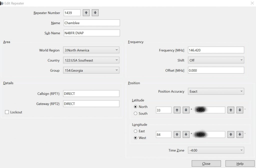
I wanted to see if I could add my DVAP Dongle hotspot to the DR list of repeaters on my Kenwood TH-D74A handheld. I could find the settings for an ICOM radio but not a Kenwood so I did a little experimenting. Here’s what worked for me:
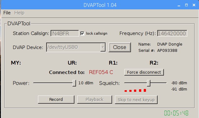
Part of the trick was using the DIRECT tag in RPT1 and RPT2. This allows me to link and unlink repeaters using the DR mode, tested on 30C and it came right through. This works with DVAP Tool V1.04 that I am running on my Raspberry Pi.
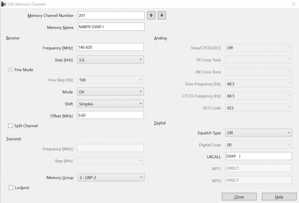
The only functionality that doesn’t seem to work is INFO and ECHO since the DVAP is looking for “DVAP I” vs. just the “I” command and “DVAP E” versus “E”. To keep that functionality, I put it in as a repeater memory.
Now I have DVAP access both ways, memory channel or DR mode. Hope this helps someone figure it out.
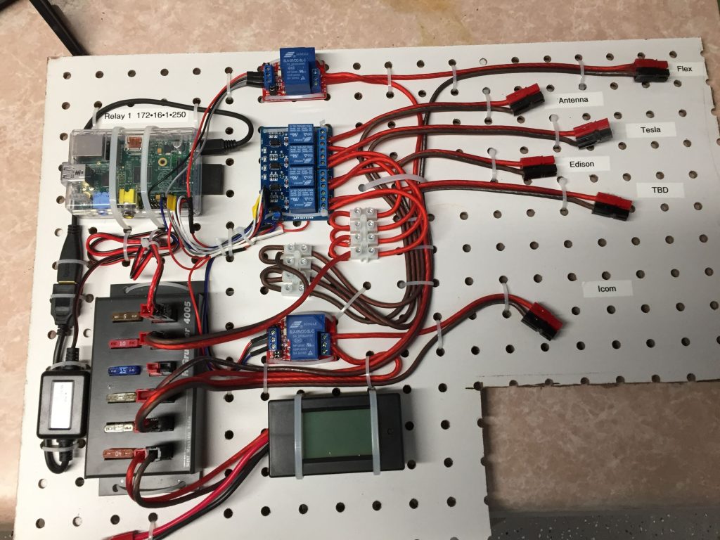
As one of my earlier projects, I set up a Raspberry Pi with some relays to control my systems remotely. This allows me to warm things up from the couch before I head to the shack, or if COVID ever goes away, to fire up the radio remotely.
2016 photo of the relay panel.
So it’s been several years since I made any updates to the Raspberry Pi that makes all that work. I remember rolling back from a Raspbian update because it broke some functionality and I wasn’t in a place to spend time on it. I finally found the time this week, 3 YEARS later.
As I write this it is January 15, 2021
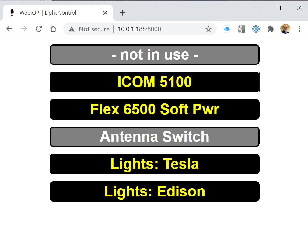
So I decided to start from the ground up with the latest version of Raspbian and reinstall WebIOPi, which is the software I am using. WebIOPi allows me to use the GPIO pins to control the relays using a web interface. I had spent a little time customizing it for my shack so I wanted to keep using it. Unfortunately it hasn’t been updated in 4 years.
My quick GUI for controlling lights and radios.
After struggling with the latest version of WebIOPi (0.7) and dealing with “invalid syntax in thread.py” and “Attribute error” issues related to my Pi 2B, I found my savior on GitHub. https://github.com/doublebind/raspi
Follow the instructions theree and you are good to go. I’ll be pleased if it will run another 3 years with no need for updates.
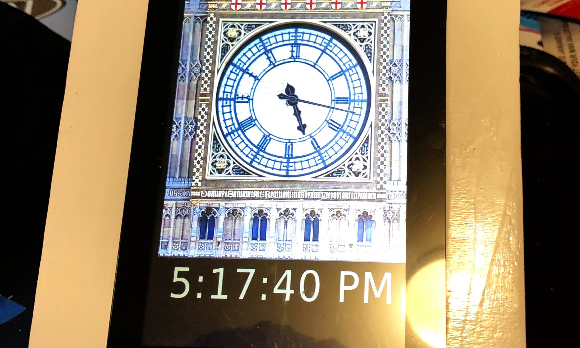
Last winter, early post retirement, I was tinkering around with one of my many clocks one day and added the chimes of Big Ben to it. Whenever I would visit my grandparents growing up, I would hear their clock that struck the Windsor Chimes and I always thought that would be a fun project.
This was fairly straightforward, I grabbed some sound files from the UK Parliament website and one other source for the 45 minute chime, and did a little editing. Work done implemented via CRON in a couple of hours, fast forward on to other things.
A few months later and I am on the phone with my mother and she hears the chimes in the background. She starts reminiscing about the sounds and her parents clock and I agree to make something for her.
This video documents the major elements of the build but here’s the parts list:
I had all the sound files to go on from my build into my exciting digital clock, so no additional work done there. One tricky bit was to get the hourly chime to trigger at about 59:40 after the hour so the big ben bell would start striking the hour right at the top of the minute. Since CRON works on minutes, I solved that by making a 59 second file. So the file starts at 59 after but plays a silent section for the first 40 seconds before the chime.
How the hourly Big Ben bell plays: CRON is programmed at xx:59 to trigger a shell script that first plays the chimes, this is the file mentioned above. It then triggers the Big Ben bell sound, and loops the appropriate number of times for each hour. Here’s an example of the code for 9 o’clock. There are 12 files, 1 for each hour.
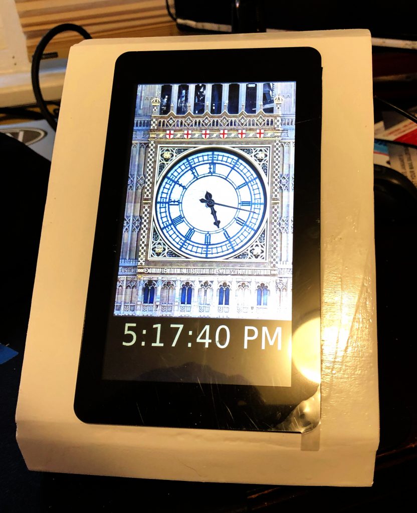
A couple of new skills for me were achieved on this project. The first was working with JavaScript clock elements for an analog clock. This came together by adding the face of the Great Clock as a background image, editing the photo for size and removing the hands from the face. I then found some similar looking clock hands and did a JavaScript analog clock overlay via HTML. Adjusting the pivot points for the hands took some time, they would drift around the clock face until set just right.
The other element to this was hardening it so it was hands off for mom. With her being 1,000 miles away, I couldn’t do a local install so it had to be right. I had her send me her WiFi info so I could pre-program it on the card. I chose USB powered speakers with an on-cord volume control so she could just lift the touch screen off the case to adjust. Also added a “kill switch” to the back for easy shut down. Finally I included a backup USB card in the case incase the current one is corrupted and I keep an image on my NAS as well if needed.
I did not put a RTC in the Pi. Partially because some of the GPIO ports I wanted we used by the Touch Screen and partly because I had the clock programmed to get NTP time via WiFi so there would be no updating needed.
The Hardware Build
I started with the standard elements I knew the Raspberry Pi 3B+. I chose the B+ because I didn’t need the horsepower of a Pi 4 for a basic display and I had one I had recently swapped out for a Pi 4 on another project. I used the 16 GB Class 10 MicroSD cards in all my Pi projects. They rarely corrupt for me when powered correctly, they offer enough space to power most projects I do, and the are small enough to back up on my NAS without completely killing storage.
I’ve used the Pi Touch Screen in a couple of other projects and it’s very easy to set up and control the display natively. In most cases I also use a commercial Pi Touch Screen stand however in this case I wanted to hide the electronics and let the clock be the focal point.
I tried to build a simple box that would hold the Pi, Screen and Speakers and I accomplished it, but I might do it differently in the future. I assembled the 4 structural elements first, the 2 sides, back and the bottom. Small birch strips held the front out from the back of the box to provide a little extra room.
On the first attempt, I made the face frame from a single piece of plywood cut in 2, so I could notch out the hole to mount the touch screen. I wasn’t really happy with the fit or the structural integrity of that, so I started with another single piece, made a small slat through which I could cut a hole for the screen with my band saw and then used putty to seal the small gap, which worked much better.
Several other holes in the box to allow for air flow, speaker audio to escape and power. I was going to put some grommets on the rough wooden holes I cut in the back but I had to give that up for time so I could get it to Mom by Christmas.
Great news is that it arrived on time and worked perfectly. We plugged it in about 10 minutes to one and by 12:59 it had synced up with the NTP server for a real time update and was playing it’s chimes.
Before it comes up…
I intentionally have not packaged this all up as a GitHub project or some other repository. I don’t own the rights to all the photos or sound files. Hopefully your build will use all the open source stuff!
Other questions on my build? Contact me on Social Media…
I was not paid in any way for this build or post. Some of the links in this post lead to shopping sites, however I make no commission. If this post helped or inspired you, consider dropping something in my tip jar.